So… Let’s say it’s Sunday afternoon in late October. You’ve just spent two days cleaning up your American Sawmill Machinery 30″ bandsaw. The whole machine is back together and looking very smart.
But wait… Where is the upper guide block? You tear through the entire shop trying to figure out where you squirelled the damn thing away. After an hour of searching, no luck. Now what?
Let’s look at how much a replacement block will cost… $300+ for one block?!? No way. That’s more than the saw cost. So, you start thinking… (this is where things go right down hill). You look at the Carter guides on the Yates American 30″ bandsaw. They are made of cheap pot metal. This stuff is extremely brittle and weak. One of the mounting screws was over-tightened at some point, causing the body to crack. I’ve always dis-liked these things. Everyone I’ve ever seen was broken or had a big chunk out of it.
Surely there must be a better design.
Back to the computer.
The first promising prospect was the Paddock # 20. It has a grooved thrust bearing at the back and a set of bearings in place of the standard guide blocks. The body is cast aluminum. I’ve seen these before and always assumed that they were antique. In reality, they are still in production today (just using the original design/pattern).

Price: $265 for the number 10. I assume the number 20 is substantially more. Definitely a better value than the Carter, but still a lot of money for a set of guides.
Then there are the Wright guides. These are the same style as the Carter guides, but the body is also cast iron rather than carboloy. These guides feature two sets of guide blocks (one above and one below the bearing).
Nice.
Good sturdy assembly. Spare parts are readily available.

Price: $289 for the number 2. Definitely the best value for the money.
Ok. So the Carter guides are out. It’s a toss-up between the Paddock and the Wright (I’d probably lean towards the Wright).
I should just order them, but I’m exceedingly cheap.
I can’t help but think that I should be able to come up with something better for less money.
Back out to the shop. I tear through all the bins and cabinets and piles of scrap metal and come up with a pile of parts:
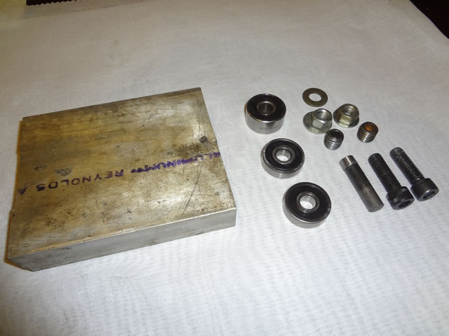
The pile consists of three bearings, an old block of aluminum scrap, some hex screws, washers, nuts, plug screws and a piece of hardened pin stock.
As with most of these projects, the plan developed as I went along.
First, I wanted the double bearing guides, rather than the typical blocks. I also wanted a thrust bearing that didn’t cause too much friction.
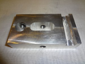
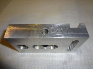
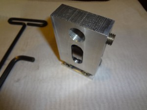
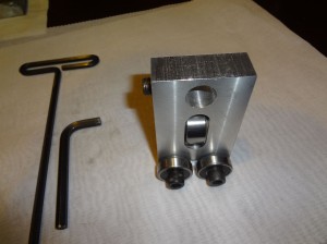
After about an hour and a half of messing around on the old Toolmaster mill, I came up with this body:

You’re looking at the back/left side of the block.
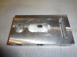
The slot in the center is for the thrust bearing. The slot at the bottom is a recess for the nuts on the hex screws. The round hole bored at the top is for the mounting stud (threaded hole is for the hex plug screw that tightens against the mounting stud. The threaded hole at the center is for the hex plug screw that pushed the hardened pin stock against the center race of the bearing.
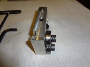
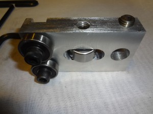
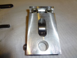
Some other views of the block below:
Right. It’s literally a block. Nothing pretty about it.
Now let’s put it together and see how it looks:
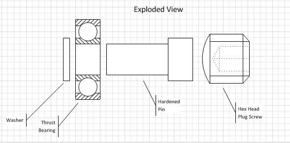
First an explanation of the mounting of the thrust bearing. I took a piece of hardened pin stock and ground it to fit into the center of the bearing. I left a slight shoulder on it so it would press aganst the center race. The bearing is placed in the slot with a washer to the left and the pin stock is pushed through. This is followed by the hex plug screw, which presses against the pin; locking the center race of the bearing against the washer and the shoulder of the pin.
Here’s an exploded view of the thrust bearing assembly:
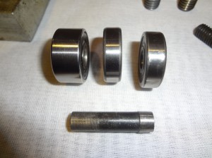
A close-up of the pin. The thrust bearing is the wider of the three (left):
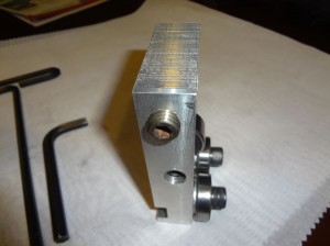
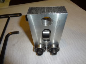
And, a number of views of the assembled guide unit:
Not bad, but will it work? The block is definitely sturdy.
To adjust for a wider blade, you just add two bearings and longer hex screws.
The bottom corners could be rounded off.
Next step is to test it on the saw.
Should be interesting.
Oh.. And now that I’ve spent all this time and effort on the replacement, you can bet that the missing guide will turn up out of nowhere.
Update: When I got home from work today I went out to the shop and mounted the new guides on the bandsaw. The short of it is that they fit and work great.
So, let’s summarize: The parts were basically free since they were just laying around the shop. It took about two hours of machine time (most of which was planning). I got a very sturdy set of guides with easily replaced components. Looks like success to me.
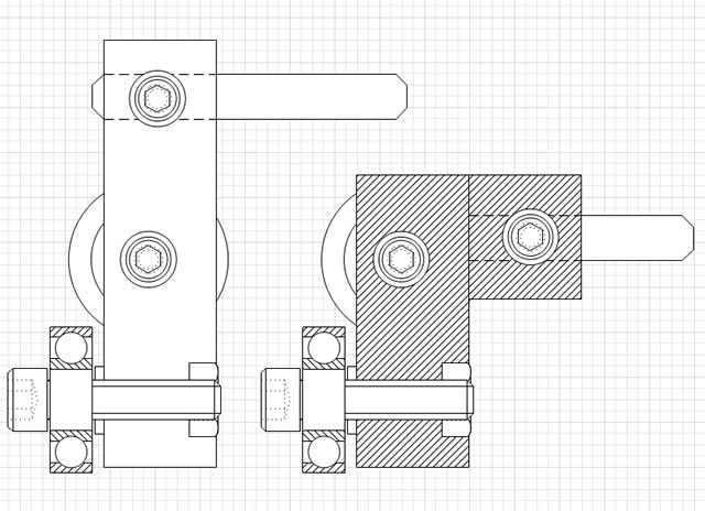
I’m already looking at improvements on the design. I think I can reduce the height of the block by 25% by moving the mounting stud lower. This means I’ll need to use a thicker piece of aluminum. A benefit of doing this is that I can use a much larger thrust bearing. This will also add some rigidity to the entire mechanism. This will very likely end up being a cast part. It looks like a pretty straightforward pattern and it’ll reduce the number of machine operations required to go from raw materials to a finished part.
Here are the drawings of the current vs. the improved design:
And finally, the video of the guides in operation can be seen here:


Great work Arthur…
My 20″ Cowan & Co bandsaw needs an upgrade in the guide department as well. I haven’t convince myself exactly how to go about it, but milling out some aluminum is something to consider.
Thanks for posting this
Jarrett,
I’m starting to think about making a pattern for this guide in a few sizes. I can get alot more flexibility out of a casting than a block of aluminum.
-Arthur